AIM:
To analyze the problems, to gather the requirements and to model the UML diagrams for Order Processing System using Rational Rose Software in CS1403 - CASE Tools Laboratory.
PROBLEM STATEMENTS:
UML DIAGRAMS:
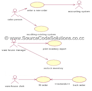
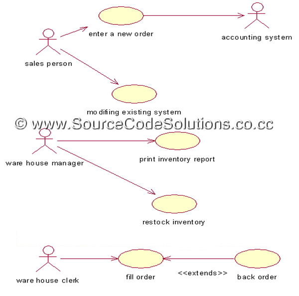
USE CASE DIAGRAM:
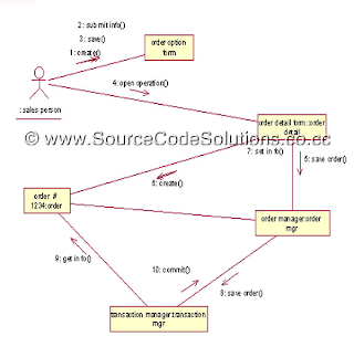
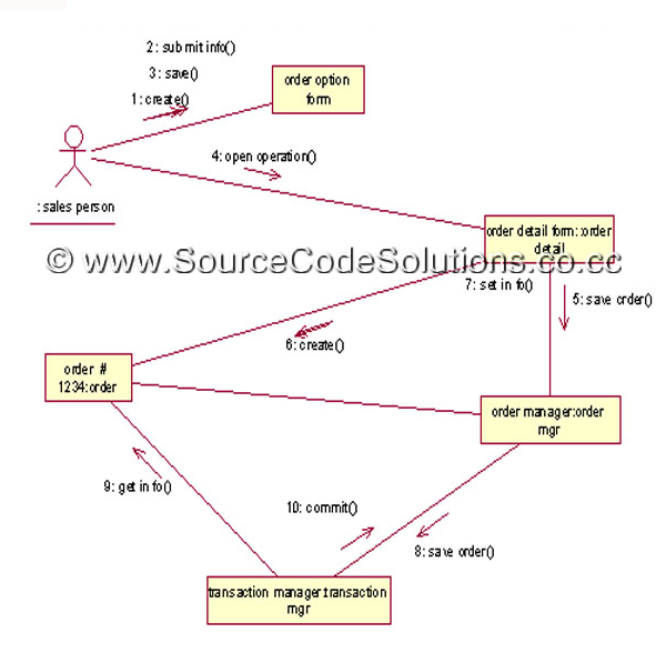
SEQUENCE DIAGRAM:

COLLABORATION DIAGRAM:
CLASS DIAGRAM:

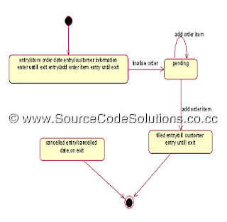
STATE CHART DIAGRAM:
ACTIVITY DIAGRAM:
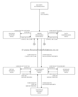
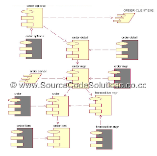
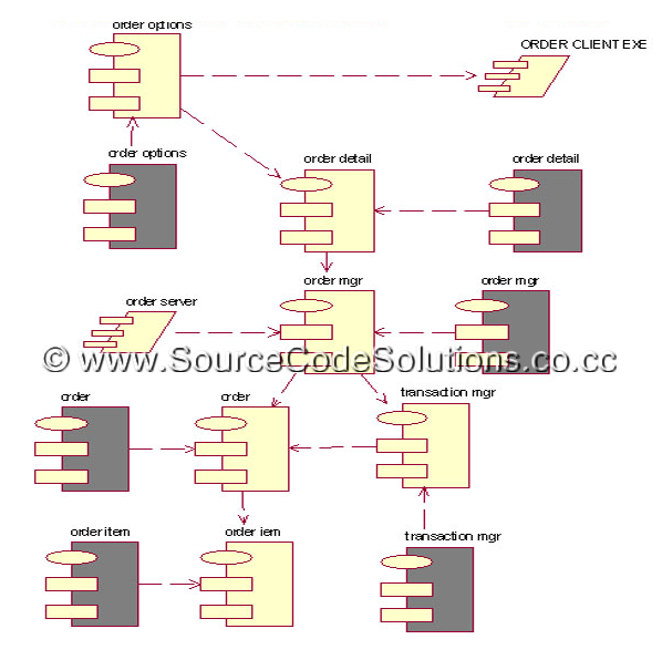
COMPONENT DIAGRAM:
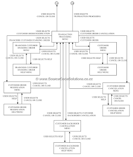
DEPLOYMENT DIAGRAM:

CONCLUSION:
Thus the UML diagrams for Order Processing System were designed using Rational Rose Software in CS1403 - CASE Tools Laboratory.
To analyze the problems, to gather the requirements and to model the UML diagrams for Order Processing System using Rational Rose Software in CS1403 - CASE Tools Laboratory.
PROBLEM STATEMENTS:
- In order to improve the operational efficiency of a mail order company, the chief executive officer is interested in computerizing the company’s business process. The major business activities of the company can be briefly described as follows:
- A customer registers to become a member by filling in the membership form and mailing it to the company. A member who has not been active (no transactions) for a period of one year will be removed from the membership list and he/she needs to re-apply for reinstatement of the lapsed membership.
- A member should inform the company of any change in personal details, such as home address, telephone numbers and etc.
- A member can place an order by filling out a sales order form and faxes it to the company or by phoning the Customer Service Assistant with the order details.
- The Customer Service Assistant first checks for the validity of membership and enters the sales order information into the system.
- The Order Processing Clerk checks the availability of the ordered items and, if they are available, holds them for the order. When all the ordered items are available, the Order Processing Clerk will schedule their delivery.
- The Inventory Control Clerk controls and maintains an appropriate level of stock and is also responsible for acquiring new items.
- If there is a problem with an order, the member will phone the Customer Service Assistant, who will then take appropriate action to follow up the particular sales order.
- Members may return defective goods within 30 days and get their money back.
- The system will record the name of staff member who handles the transaction for future follow up action.
UML DIAGRAMS:
USE CASE DIAGRAM:
SEQUENCE DIAGRAM:

COLLABORATION DIAGRAM:
CLASS DIAGRAM:

STATE CHART DIAGRAM:


ACTIVITY DIAGRAM:

COMPONENT DIAGRAM:
DEPLOYMENT DIAGRAM:

CONCLUSION:
Thus the UML diagrams for Order Processing System were designed using Rational Rose Software in CS1403 - CASE Tools Laboratory.
2 comments
Write commentsNice diagrams for order processing system.i really like that.but just a confusion on some points.otherwise nice work.order processing
Replythe context diagram, zero-level DFD???
ReplyEmoticonEmoticon